What theorem underlies all the calculations?
Getting started
Let's begin with some information about you
The information you introduce in this web app remains in your device and will not be sent or stored anywhere else. Please use the generate PDF function to save your work. Only if the server is not reachable (see status in the dashboard), safe your work via .txt and .png downloads
Registration ID
Name
Test bench
| Variable name | Description |
|---|---|
| raD1ACtrlSetp | Setpoint (in deg) for angle \(\theta_1\) of servomotor 1 |
| raD2ACtrlSetp | Setpoint (in deg) for angle \(\theta_2\) of servomotor 2 |
| raD3ACtrlSetp | Setpoint (in deg) for angle \(\theta_3\) of servomotor 3 |
| raD4ACtrlSetp | Setpoint (in deg) for angle \(\theta_4\) of servomotor 4 |
| raD5ACtrlSetp | Setpoint (in deg) for angle \(\theta_5\) of servomotor 5 |
| raD6ACtrlSetp | Setpoint (in deg) for angle \(\theta_6\) of servomotor 6 |
| raD7ACtrlSetp | Setpoint (in deg) for angle \(\theta_7\) of servomotor 7 |
| raD1CurrMeasAct | Actual measured current of servomotor 1 in mA |
| raD2CurrMeasAct | Actual measured current of servomotor 2 in mA |
| raD3CurrMeasAct | Actual measured current of servomotor 3 in mA |
| raD4CurrMeasAct | Actual measured current of servomotor 4 in mA |
| raD5CurrMeasAct | Actual measured current of servomotor 5 in mA |
| raD6CurrMeasAct | Actual measured current of servomotor 6 in mA |
| raD7CurrMeasAct | Actual measured current of servomotor 7 in mA |
| raO1PosAct | Actual [\(x\), \(y\), \(z\)] coordinates of link O1 |
| raO2PosAct | Actual [\(x\), \(y\), \(z\)] coordinates of link O2 |
| raO3PosAct | Actual [\(x\), \(y\), \(z\)] coordinates of link O3 |
| raO4PosAct | Actual [\(x\), \(y\), \(z\)] coordinates of link O4 |
| raO5PosAct | Actual [\(x\), \(y\), \(z\)] coordinates of link O5 |
| raO6PosAct | Actual [\(x\), \(y\), \(z\)] coordinates of link O6 |
Research of the kinematic parameters of the robot arm
At this stage you will gain an understanding of the principles of the robot`s movement.
Use control sliders to change the robot`s position and move the gripper to the aimed object.
Order of the experiment
- Study the composition and technical characteristics of the laboratory setup, as well as the kinematic structure of the robot, following the guidelines:
- Access the laboratory experiment page (Laboratory experiment #1) and enter the unique access code on the "Dashboard" control console, provided by the instructor (Session Code), by clicking the "Request Control" and "Apply" buttons;
- Enter student`s personal data on the "Home" tab. After this step, the participant is granted the right to control the robot (experiment).
- Activate the robot's joint servomotors by using the sliders in the "Run Experiment" control window. Observe through the webcam as the robot gradually changes its position in space to grasp the object in front of it.
- After successfully grasping the object, record the grip manipulator's position data (Coordinates of the grip [x, y, z]) manually or use the button to transfer the values automatically. This information will be automatically transferred to the corresponding fields for the report.
- Capture a screenshot of the robot's position using the built-in "Take a snapshot" button.
- Answer the control questions on the laboratory experiment page.
- Proceed to the next experiment.
Run the experiment
| Coordinates of the grip [\(x\), \(y\), \(z\)] |
|---|
|
\(O_6\)

|
Q1
The Denavit-Hartenberg parameters in robotics
In this experiment the main goal is study and use of the Denavit-Hartenberg parameters
Quick memo on the formulas from the methodical guidelines:
\(\begin{bmatrix} x_{06_{i-1}} \\ y_{06_{i-1}} \\ z_{06_{i-1}} \\ 1 \end{bmatrix}=M_i\times\begin{bmatrix} x_{06_{i}} \\ y_{06_{i}} \\ z_{06_{i}} \\ 1 \end{bmatrix}\)
\(M_i=\begin{bmatrix}\cos\theta_i & -\sin\theta_i\cos\alpha_i & \sin\theta_i\sin\alpha_i & r_i\cos\theta_i \\\sin\theta_i & \cos\theta_i\cos\alpha_i & -\cos\theta_i\sin\alpha_i & r_i\sin\theta_i \\0 & \sin\alpha_i & \cos\alpha_i & d_i \\0& 0 & 0 & 1 \end{bmatrix}\)
Order of the experiment
- Study the composition and technical characteristics of the laboratory setup, as well as the kinematic structure of the robot, following the guidelines:
- Go to the laboratory experiment page (Laboratory experiment #2) and enter the unique access code on the "Dashboard" experiment control console, which was provided by the teacher (Session Code), by clicking the "Request Control" button and the "Apply" button.
- Enter student`s personal data on the "Home" tab. After this step, the participant is granted the right to control the robot (experiment).
- Set the position of the robot in the space of the working area by entering arbitrary values of the angles, using the fields for entering the values of the "Angles, deg" window, taking into account the specified limitations of the working angles of the robot in the "Limit range, deg" field. To access the control window, press the "Run Experiment" switch and update the position of the robot, use button to set previous angles as a setpoint, press the "Update setpoint" button.
- Using the button in the "Coordinates of the grip [x, y, z]" field, automatically transfer the robot's grip coordinates to the \(real O_6\) field from the "Coordinates of the grip" window.
- Get the coordinates of the robot joints using the "Run Experiment" panel. Calculate the transfer matrices according to the formulas given in the methodological instructions, using the values of the obtained angles.
- Calculate the coordinates of the joints of the manipulator in the coordinate system relative to the point \(O_6\)
- Manually enter the calculated grip coordinates to the \(math O_6\) field from the "Coordinates of the grip" window.
- Take a screenshot of the robot's position using the "Take a snapshot" button.
- Answer the control questions on the laboratory experiment page.
- Proceed to the next experiment.
Run the experiment
| Angles, deg | Limit range, deg | Coordinates of the grip [\(x\), \(y\), \(z\)] |
|---|---|---|
|
\(\theta_1\)
\(\theta_2\)
\(\theta_3\)
\(\theta_4\)
\(\theta_5\)
\(\theta_6\)
\(\theta_7\)
|
|
\(real O_6\)
\(math O_6\)
|
Q2
Use of trigonometry in robotics
At this stage you will learn to use position of the robot to get angular information
Quick memo on the formulas from the methodical guidelines:
|

|
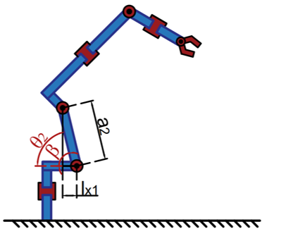
| \(\theta_2\in x\leq \angle90\) \(\theta_2=\beta\) | \(\theta_2\in x > \angle90\) \(\theta_2=\pi-\beta\) |
|

|
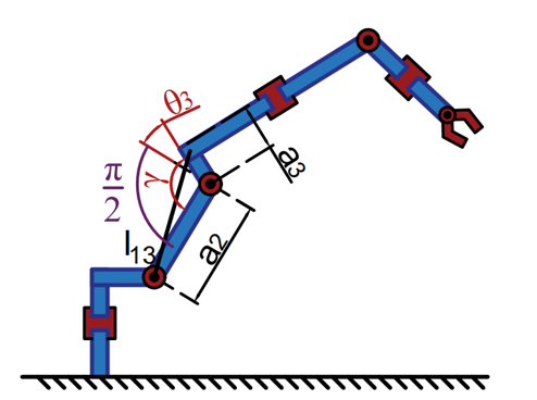
| \(\theta_3\in x\leq \angle90\) \(\theta_3=\gamma-\frac{\pi}{2}\) | \(\theta_3\in x> \angle90\) \(\theta_3=\frac{3\pi}{2}-\gamma\) |
|
|
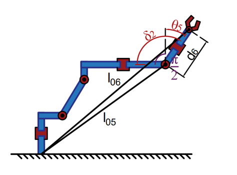
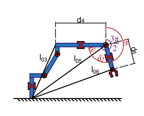
| \(\theta_5\in x\leq \angle40\) \(\theta_5=\delta_2-\frac{\pi}{2}\) | \(\theta_5\in x> \angle40\) \(\theta_5=\frac{3\pi}{2}-\delta_1-\delta_2\) |
Order of the experiment
- Study the composition and technical characteristics of the laboratory setup, as well as the kinematic structure of the robot, following the guidelines:
- Go to the laboratory experiment page (Laboratory experiment #3) and enter the unique access code on the "Dashboard" experiment control console, which was provided by the teacher (Session Code), by clicking the "Request Control" button and the "Apply" button.
- Enter student`s personal data on the "Home" tab. After this step, the participant is granted the right to control the robot (experiment).
- Using the object management sliders, on the “Run Experiment", set the free position of the work in the space of the working area, controlling the process through a webcam. At the same time, you should take into account the conditions that links 4 and 6 must be in a position of 90 degrees.
- Take a screenshot of the received manipulator configuration using the "Take a snapshot" button.
- Transfer the coordinates of the points from the "Run Experiment" window to the "Link coordinates [x, y, z]" response field by clicking the button to fix the instantaneous values of the coordinates.
- Calculate the angles of movement of the corresponding links of the robot using methodical instructions.
- Enter the obtained results in the answer field "Angles,deg".
- Answer the control questions on the laboratory experiment page.
- Go to the "Save work" page and generate an automatic report. Then save the report to your device.
Run the experiment
| Coordinates of the links [\(x\), \(y\), \(z\)] | Angles, deg |
|---|---|
|
\(O_1\)
|
\(\theta_1\)
|
|
\(O_2\)
|
\(\theta_2\)
|
|
\(O_3\)
|
\(\theta_3\)
|
|
\(O_4\)
|
\(\theta_4\)
|
|
\(O_5\)
|
\(\theta_5\)
|
|
\(O_6\)
|
\(\theta_6\)
|
Q3
Save your work
Date
Key
Keep in mind that adBlockers may prevent this feature.
Generate my report as Textfile (only at a pinch!)
Download first screenshot
Download second screenshot
Download third screenshot
Dashboard
Status:
Server Status Info:
Remaining control time for master:
Total Students in Queue:
| min | max | |
| min | max | |
| min | max | |
| min | max | |
| min | max | |
| min | max | |
| min | max | |
\(O_1\)
\(O_2\)
\(O_3\)
\(O_4\)
\(O_5\)
\(O_6\)